TUTORIAL FOR SKIN PROTECTION ASSISTANT
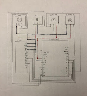
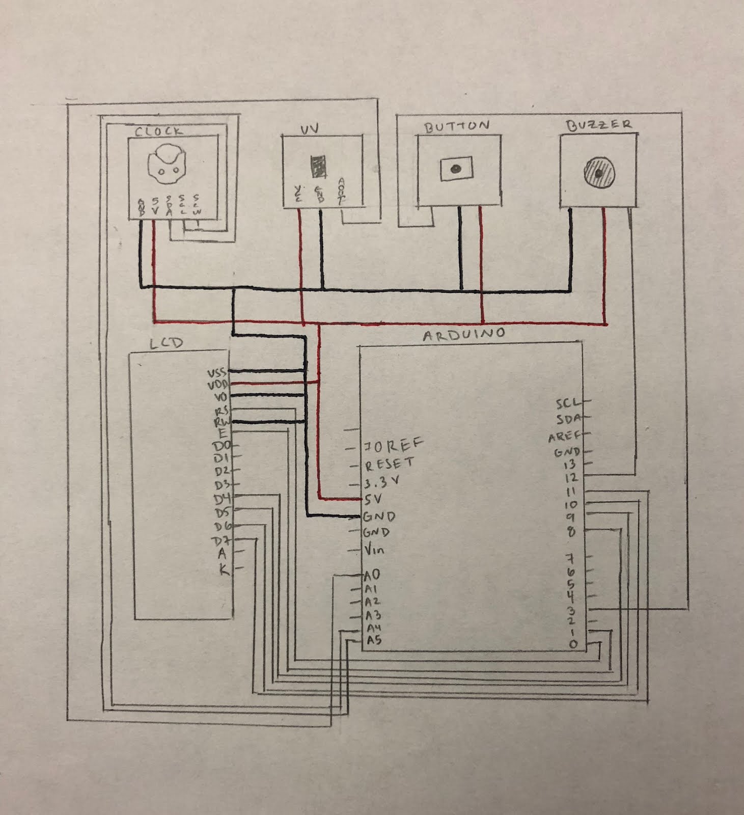
\The connections for LCD to Arduino are given below:
1. PIN1 or VSS to ground
2. PIN2 or VDD or VCC to +5v power
3. PIN3 or VEE to ground (gives maximum contrast best for a beginner)
4. PIN4 or RS (Register Selection) to PIN0 of ARDUINO UNO
5. PIN5 or RW (Read/Write) to ground (puts LCD in read mode eases the communication for user)
6. PIN6 or E (Enable) to PIN1 of ARDUINO UNO
7. PIN11 or D4 to PIN8 of ARDUINO UNO
8. PIN12 or D5 to PIN9 of ARDUINO UNO
9. PIN13 or D6 to PIN10 of ARDUINO UNO
10. PIN14 or D7 to PIN11 of ARDUINO UNO
\The connections for LCD to Arduino are given below:
1. GND- GND
2. VCC-VCC
3. Output -A0
\The connections for the buzzer and button to Arduino Uno
Button:
1. LEFT PIN TO PIN 3
2. MIDDLE PIN TO GROUND
3. RIGHT PIN TO 5V
Buzzer:
1. LEFT PIN TO GROUND
2. MIDDLE PIN TO 5V
3. RIGHT PIN TO PIN 12
\The connections for clock
1. PIN 1(GND) TO GROUND
2. PIN 2(5V) TO 5V
3. PIN 3(SDA) TO A4
4. PIN 4(SCL) TO A5
5. PIN 5(SQW) TO N/A
The Arduino Uno board as well as associated sensors is powered by a battery pack.
No comments:
Post a Comment